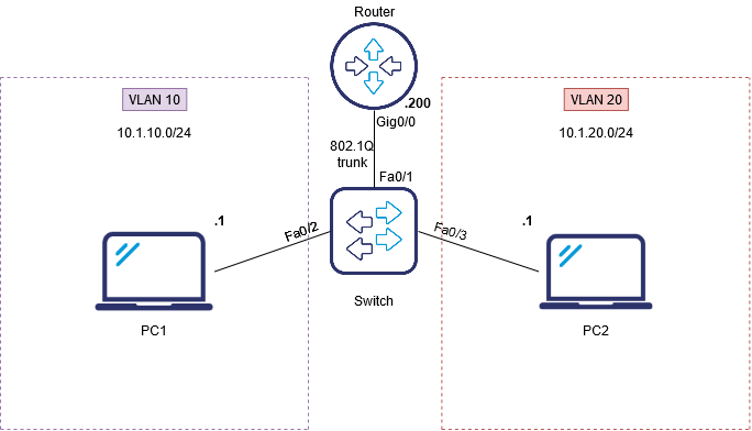
A router on a stick is one of the ways to allow routing between VLANs. That kind of a setup consists of a router and a switch connected through one Ethernet link configured as an 802.1q trunk link. Such a configuration is typical in networks where no layer-3 switch exists. But first, let’s find out why it is so.
Sub-interfaces
When configuring new VLANs on switch ports, we split the broadcast domain in which it was placed into smaller VLAN-limited sections. The basic switch can not route packets between broadcast domains. It is well known that the router is a device that routes packets and separates broadcast domains.
A layer 3 OSI model solution is, therefore, required to allow communication between devices from different VLANs. One example is a router on a stick (which we’ll cover in this material), but there are also solutions such as SVI (virtual switch interface) or one router interface per VLAN.
The sub-interface is a key feature of the router on a stick. It is configured for each network on the router.
Sub-interfaces are the logical elements of a physical interface. Thanks to this approach it is not necessary to use N physical interfaces of the router on N VLANs. Instead, there is a trunk link between a switch and a router, so marked packets go to the router. After that, the router removes the labels and previews the routing table.
It is essential to set up 802.1Q encapsulation on each sub-interface and corresponding VLAN tag as well because after matching the entry, the packet is encapsulated according to the method configured on the output interface.
A router on a stick configuration
Suppose we have a network of two computers in different VLANs. We have VLAN 10 and VLAN 20. To enable communication between PC1 from VLAN 10 and PC2 from VLAN 20, we can use a router on a stick approach. The topology is as follows:
Let’s start by configuring the port connecting the switch to the router. Remember that the connection between the router and the switch must be set via the trunk link:
Switch#configure terminal

Switch(config)#int Fa0/1

Switch(config-if)#switchport mode trunk

Switch(config-if)#switchport trunk encapsulation dot1q

Switch(config-if)#spanning-tree portfast trunk
Then, let’s create the required VLANs and configure the access ports for DTE:
Switch#configure terminal
Switch(config)#vlan 10
Switch(config)#vlan 20
Switch(config)#int Fa0/2
Switch(config-if)switchport mode access
Switch(config-if)#switchport access vlan 10
Switch(config-if)#exit
Switch(config)#int Fa0/3
Switch(config-if)#switchport mode access
Switch(config-if)#switchport access vlan 20
In the end, we start our router configuration by setting sub-interfaces. On the port connecting the router with the switch, we configure sub-interfaces for each VLAN.
We also set 802.1Q encapsulation with VLAN number to which the sub-interface will belong. Sub-interfaces are the logical instance of the physical port Gig0/0 (in this case). The IP address is then assigned from the pool for the specific VLAN.
Router(config)#interface GigabitEthernet0/0.1
Router(config-subif)#encapsulation dot1q 10
Router(config-subif)#ip address 10.1.10.200 255.255.255.0
Router(config-subif)#interface GigabitEthernet0/0.2
Router(config-subif)#encapsulation dot1q 20
Router(config-subif)#ip address 10.1.20.200 255.255.255.0
Router(config-subif)#int Gig0/0
Router(config-if)#no shutdown
Author: Karol Piatek

