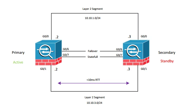
ASA Failover is intended for improving high availability of the firewall solution. ASA
Failover technology uses 2 units in failover pair. We can configure Failover in two modes:
- Active Standby Failover
- Active Active Failover
ASA Failover rules:
- Maximum of 10 ms Round Trip Time between units
- Each logical interface must be in same L2 segment
- Each logical interface is IP addressed (active IP and standby IP)
- IP and MAC (virtual) is always maintained by the current active Unit
- When failover occurs, ASA standby assumes active IP and MAC and sends
- Gratuitous ARP on each interface to recalculate L2 subnets.
- Failover interface is required and intended for configuration replication and keep alive unit pooling
- Stateful interface is optional and intended for live session replication between
units.
ASA Failover – Active Standby

Active Standby failover means that two units are working in active – standby configuration where active state is always present on one of the failover pair. The other one is standby. Standby has identical configuration as active and pools an active unit with keep alive packets. Based on defined timeout (5 seconds pooling interval and 3 times repeats, configurable) failover condition is checked. If failover condition is meet, standby unit becomes active and acquires active IP address and MAC, standby IP and MAC goes to standby Unit. Basic configuration of failover is presented below.
Primary Unit:
failover

failover lan unit primary

failover lan interface FAILOVER GigabitEthernet0/6

failover link STATEFULL GigabitEthernet0/7

failover interface ip FAILOVER 192.168.1.1 255.255.255.252 standby 192.168.1.2

failover interface ip STATEFULL 192.168.2.1 255.255.255.252 standby 192.168.2.2
Secondary Unit:
failover

failover lan unit secondary

failover lan interface FAILOVER GigabitEthernet0/6

failover link STATEFULL GigabitEthernet0/7

failover interface ip FAILOVER 192.168.1.1 255.255.255.252 standby 192.168.1.2

failover interface ip STATEFULL 192.168.2.1 255.255.255.252 standby 192.168.2.2
TIP: to switch-on failover, use command failover on both units.
- The active unit is determined by these:
- If a unit boots and detects a peer already operative as active, it becomes the
standby unit.
- If a unit boots and does not detect a peer, it becomes the active unit.
- If both units boot simultaneously, the primary unit becomes the active unit,
and the secondary unit becomes the standby unit.
More in Cisco Firepower Online Training
Let us guide you through Cisco Firepower Threat Defense technology (FTD) along with Firepower Management Center (FMC) as security management and reporting environment.
Author: Marcin Bialy


