Introduction to pathloss
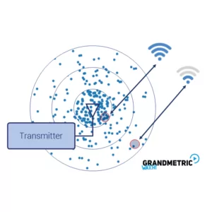
A transmitter generally radiates the signal which has a specific power using an antenna. This signal travels in the environment as an electromagnetic wave and suffers from a phenomenon known as pathloss. This wave isn’t aware of the exact route to the receiver and hence once transmitted propagates in the direction where the antenna directs the signal. The receiver captures a certain fraction of transmitted power depending on different factors such as distance, obstacles etc, and decodes it.
Electromagnetic wave propagates and travels further and further away. Due to this, the initial power at which the transmitter transmitted the signals spreads over a larger area. At the beginning whole transmitted power is contained in a small “bubble”. If the receiver is close to the transmitter it can capture more power. If the receiver is further away from the transmitter, the density of the power is smaller and the receiving antenna captures only small fraction of the transmitted power. The figure below depicts this phenomenon:
Theoretical background
As we already know, the power of the signal reduces as the signal propagates. But what is the relation between the loss and the distance? Is the distance only variable in this equation?
Let’s take a look on following figure:
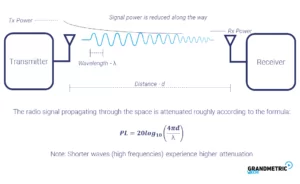
There are several parameters involved: distance, wavelength and the transmit power. Pathloss (PL) depends on distance and wavelength. The above formula confirms our observation, that greater distance means lower power. What we didn’t previously investigate is the wavelength. The loss is higher for shorter wavelengths. This means that high frequency signal (i.e. short wavelength) travels for a shorter distance than a low frequency signal. That is one of the reasons why 802.11ad utilizing 60GHz can be used only in a single room.
Power loss does not depend on transmitted power. If the loss of the path is 20dB it will affect a strong signal in the same manner as a weak signal. The difference will be visible in the received power though. If we send weak signal and it will get decreased even more, we won’t be able to decode it.
Simulation results
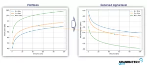
In the figure below you can see the values of the pathloss for different frequencies. You can notice how different frequencies are affected along the traveled distance. Figure on the right presents corresponding received power. From this we can estimate the range of the system if we know required received signal power.
Other materials
To see other posts on network and wireless fundamentals see our explained section.
To subscribe to our mailing list for our online platform where you can learn all this and more visit GrandmetricWatch. We will inform you when it will be live.


