After discussing the main wireless transmission concept (How wireless works?), main channel propagation phenomena (What is pathloss? and What is shadowing?), and antenna configurations (What is MIMO?), let’s now take a look at one of the most commonly used transmission scheme nowadays, namely Orthogonal Frequency Division Multiplexing (OFDM). But, before we explain why do we use it and what are its principles, let’s firstly take a look on another radio channel phenomenon namely, multipath.
Multipath channel recap
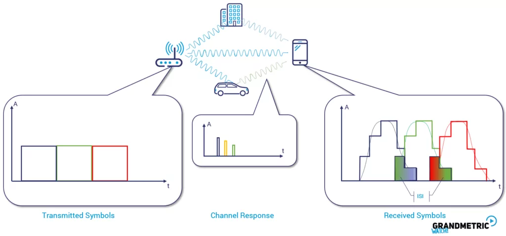 We know, in the radio channel, the radio signal is received through multiple paths, resulting from separate channel „taps” (see the figure above). When we transmit a single rectangle symbol, it shows up at the receiver as a combination of (in this case 3 copies) that are differently delayed and attenuated. When there are multiple consecutive symbols, one right next to another – this results in interference from the previous symbol to the next – Inter-Symbol Interference (ISI).
Inter-Symbol Interference
Lets look at the example of the actual impairments (see figure below). Let’s assume, we have 3 symbols transmitted within 1 second (3 sym/sec), each carrying, for simplicity, a single bit. (Otherwise each symbol can carry multiple bits, as in the case of QPSK/QAM mapping).
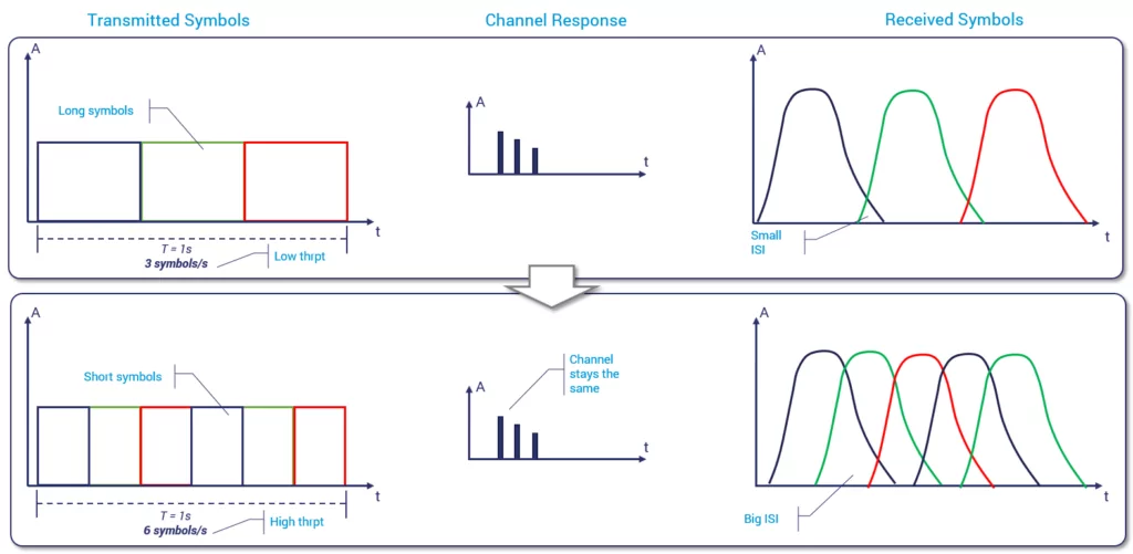
They travel through a channel with 3 „taps” that results in the spread symbols with a duration longer than the duration of individual symbol (T) – resulting in ISI. When the symbols are long (upper part of the figure) – meaning low thrpt – the ISI is small i.e., we are able to decode the signal, as majority of the power is received without interference.
Now, we want to transmit more symbols within this 1 second, so we put there 6 symbols (lower part of the figure). This requires that each symbol is shorter, but giving us higher thrpt (2x higher compared to the upper case). The channel does not change only due to the transmission characteristic of the symbol, so the same symbol dispersion (smearing) is seen. However, in this case, the symbols are shorter, so the impairment is more severe i.e., larger part of the symbol is spreading out to the subsequent symbols. Therefore, as we can see, the green symbol is pretty much impaired along its whole duration (by blue and red symbols). Thus, we do not have any part of the symbol being „clear from interference”.
Frequency selective fading
Let’s now take a look on the other dimension of the signal representation i.e. frequency. As we know from the theory – long symbols result in narrow Bandwidth (BW = ~1/T), and the multipath channel response is always selective (i.e., the different frequency components within a symbol are modified differently). In the frequency domain, as the signal propagates through the channel, we multiply each individual frequency „tap/component” of the signal with the corresponding frequency tap of the channel frequency response (see figure below).
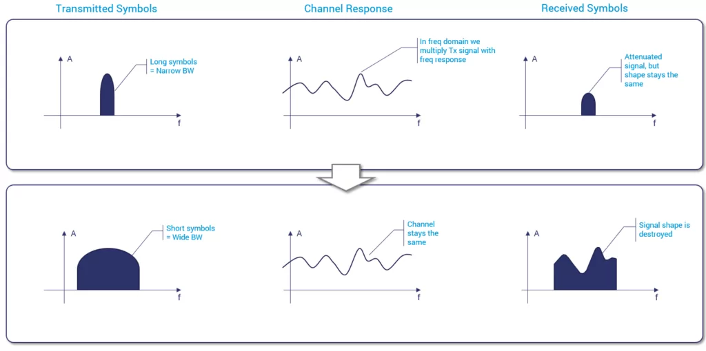
If the symbol is long enough – i.e., has narrow bandwidth (upper part of the figure), it is influenced by the channel, but only amplified or attenuated with a single value, while its shape stays still the same (this means that the channel is flat).
In the second example (lower part of the figure), we transmit faster (i.e., using short symbols), which means that the symbol/system BW is wider (as the same principle, BW = ~1/T, is used). The signal goes through the same channel, and its individual frequencies are multiplied by the corresponding elements in the channel frequency response, thus all the individual frequency components are modified according to the shape of the channel frequency response. The resulting received signal shape is destroyed (compared to the original signal frequency representation on the left side of the figure), and makes it hard to revoke the original shape without complex estimators and receiving algorithms.
OFDM principles
Taking now into account our considerations above, on one hand we want long symbols – because long symbols mean low impact of the ISI, and low impact of the frequency selectivity – BUT at the same time, we would like to have high throughput – which is not possible through single carrier modulation, where data symbols (BPSK/QPSK/QAM) transmitted one after another have to be very short – because of increasing impact of the channel.
As a side comment, it is imporant to note that the long or short symbols are always with respect to the channel impulse response (and its dispersion):
- which means that a short symbol in mountain environment (where the channel impulse response, CIR is long),
- can be „perceived” as long in the office environment (that does not impact the signal so much due to short CIR).
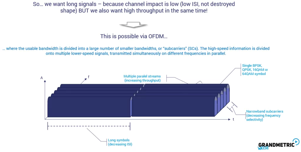
This is where OFDM comes as a solution. It, simply speaking, combines all requirements so that we get:
- long symbols – decreasing ISI,
- narrow BWs – avoiding frequency selectivity,
- high throughput.
This is achieved by the facts shown on the figure above, namely:
- the usable bandwidth is divided into a large number of smaller bandwidth portions, or “subcarriers” (SCs);
- the high-speed information is split onto multiple lower-speed signals, transmitted simultaneously on different frequencies (SCs) in parallel.
Let’s now look at the analogy between single carrier and multi carrier transmission, by looking at the shipment of the goods via trucks (see the figure below).
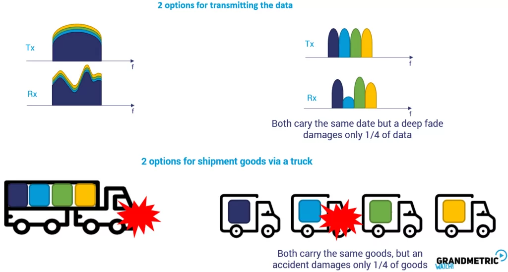
When we transmit a wideband signal (i.e., short symbols, one after another), this is analogous, to a big truck carrying several packages (left part of the figure). In contrary, multi-carrier transmission is analogous to shipment goods using several smaller cars, each carrying a single package (right side of the figure).
Now, when the signal goes through the „fading channel” it is distorted (as explained in the previous section before), this can be seen as a road accident: if the same road accident happens to both types of shipment, in the case of a truck the whole transport is destroyed, while in the case of smaller cars carrying the separate packages, only one will be destroyed. This is analogical to a single deep fade, by which only one subcarrier (part of data) is destroyed (i.e. not receivable) in a multi-carrier system, while whole transmission is destroyed in a single-carrier wideband system.
Other materials
To see other posts on network and wireless fundamentals – for example about pathloss, shadowing or MIMO – see our explained section.
To subscribe to our mailing list for our online platform where you can learn all this and more (for example all the details on OFDM transmission) visit GrandmetricWatch.


 We know, in the radio channel, the radio signal is received through multiple paths, resulting from separate channel „taps” (see the figure above). When we transmit a single rectangle symbol, it shows up at the receiver as a combination of (in this case 3 copies) that are differently delayed and attenuated. When there are multiple consecutive symbols, one right next to another – this results in interference from the previous symbol to the next – Inter-Symbol Interference (ISI).


