This article is the first part in the series about SD-WAN technology where we learn step by step what exactly Software Defined WAN (SD-WAN) is, how to build and use it, how and why using this concept could be beneficial for enterprises or even service providers and how to transform the current enterprise WAN to a SD-WAN solution. We are going to start with looking closely at Cisco Viptela product, however later on, we will describe other SD-WAN platforms in a similar manner.
Scope: Following article focuses on Cisco Viptela SD-WAN functional components and basic connectivity concepts.
Software Defined WAN. Besides the slogans.
So what is so special about the new Software Defined WAN concept besides the many marketing slogans like “Redefining Networks for Cloud era” or “Transport independent secure fabric” or where the “66% cost reduction” comes from? First of all when we talk about SDWAN we can think of it as the practical enforcement of Software Defined Network (SDN) concept. The main point in SDN approach is network data plane and control plane disaggregation and flavour of API-based open networking for better interoperability between the systems and processes automation. Executing the SDN concept, in SD-WAN everything related to control plane logic is transferred to central brain which is called the controller. There is also management plane and API-enabled body for management purposes and CPE instances (physical or virtual routers) that execute the data plane part (also known as forwarding plane). Looking at the history of WANs we have been configuring (even still today we do) hop by hop, device by device, QOS classes, policy maps, routing, security features with great attention, but still doing some mistakes, having large administration overhead and need for network engineers expertise. With SD-WAN we can avoid significant part of above having at the same time nice bunch of additional features.
Cisco Viptela SD-WAN components.
In Cisco Viptela solution the role of network controller is played by vSmart controller (located in the cloud). We see vEdges that are CPEs and every vEdge has to be connected with vBond and vSmart to kick off full operability. vEdge can be physical or virtual and they are typically located at customer premises but can also be installed on private and public clouds. The vManage is the tool or simply kind of a dashboard that helps administrators to clearly define WAN communication rules and manage policies from a graphical interface. Using vManage, administrators are allowed to construct different topologies depending on their needs, such as branches with single or dual MPLS/Internet lines, hub and spoke topologies or spoke to spoke connectivity. Below picture shows how the functional modules are connected to each other.
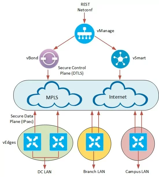
The whole concept consists of four elements:
- vBond – initiates the bring up process of every vEdge device, at the first step it creates secure tunnel with vEdge and informs vSmart and vManage about its parameters like for instance ip address. It has to be fully connected with every device.
- vSmart – this is a controller for your network, it is responsible for managing all control and data policies by using special Overlay Management Protocol (OMP).
- vEdge – router which receive complete control and data policies from the vSmart, it is able to run routing protocol like OSPF, BGP to create connectivity on LAN side but also with MPLS provider if necessary. It establishes secure IPSec tunnels with others vEdges depending on selected topology.
- vManage – fully manageable centralized portal to run and operate software defined network (SD-WAN).
Every piece of above list plays a separate significant role in the whole puzzle, however to configure and operate the network typically we have to spent most of the time on vManage.
Looking closely at each component.
Let’s firstly look on a vEdge device, what parameter we should predefine to be able to use zero touch provisioning functionality. The requirements are vBond IP address to which we have to build the secure control connectivity, organization name and basic external interface WAN configuration. It can be set statically or allocated dynamically. We should do it inside VPN service which is designed to serve as a transport purpose. We have also special VPN 512 only for management purpose and others 1-511 for common use cases. Additional parameters we will apply with template directly from the vManage portal. To successfully connect vEdge device to the cloud based piece of infrastructure they are staged with pre-generated private and public keys together with certificate signed by Avnet. The certificate is loaded into TPM chip and has a root CA trust chain for Symantec Root CA.
Connecting vEdge to vBond
vEdge base configuration:
System

 organization-name „NAME”

 vbond b.b.b.b

!

vpn 0

 interface eth0

  ip address 1.2.3.4/xx or ip dhcp-client

  !

  no shutdown

 !

 ip route 0.0.0.0/0 x.x.x.x
In few words, vEdge exchanges certificate with vBond which also validates vEdge serial number and chassis identifier. Once this part is completed vBond informs vSmart and vManage of newly attached device IP address. Finally it shares to vEdge a complete list of vSmart and vManage instances. Then the just provisioned DTLS tunnel between vBond and vEdge is terminated.
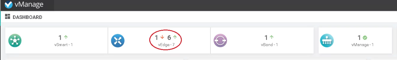
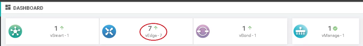
Picture 1 – vManage status before vEdge attachment
vedge# show control connections

PEER    PEER PEER            SITE       DOMAIN PEER                                    PRIV  PEER                                    PUB                                               GROUP

TYPE    PROT SYSTEM IP       ID         ID     PRIVATE IP                              PORT  PUBLIC IP                               PORT  LOCAL COLOR     STATE           UPTIME      ID

--------------------------------------------------------------------

vbond   dtls -               0          0      198.18.1.11                             12346 198.18.1.11                             12346 biz-internet    connect                     0
Above control connection is created between vEdge and vBond during the initialization process, at the beginning device has only single tunnel with vBond, though when the process completes the device will pick up full control connectivity with vSmarts and vManages over every possible means of transport.
vEdge control connections to vSmart and vManage
vedge# show control connections

                             PEER                                          PEER                                              CONTROLLER

PEER    PEER PEER            SITE       DOMAIN PEER                                    PRIV  PEER                                    PUB                                               GROUP

TYPE    PROT SYSTEM IP       ID         ID     PRIVATE IP                              PORT  PUBLIC IP                               PORT  LOCAL COLOR     STATE           UPTIME      ID

--------------------------------------------------------------------

vsmart  dtls 12.12.12.12     10         1      198.18.1.12                             12346 198.18.1.12                             12346 biz-internet    up              0:00:00:32  0

vsmart  dtls 12.12.12.12     10         1      198.18.1.12                             12346 198.18.1.12                             12346 mpls            up              0:00:00:18  0

vmanage dtls 10.10.10.10     10         0      198.18.1.10                             12346 198.18.1.10                             12346 biz-internet    up              0:00:00:32  0
Configuration templates
Later we should define a template for rest important part of configuration like users VPNs or management protocols. Then we could attached it to device as per below picture.
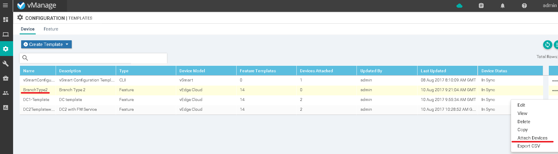
Picture 2 – Template attachment process
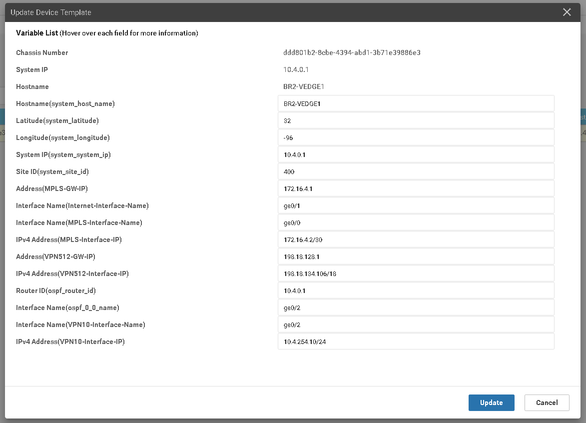
Picture 3 – Template fulfilment process
During this process we could assign and modify dynamic variables which could vary based on location.
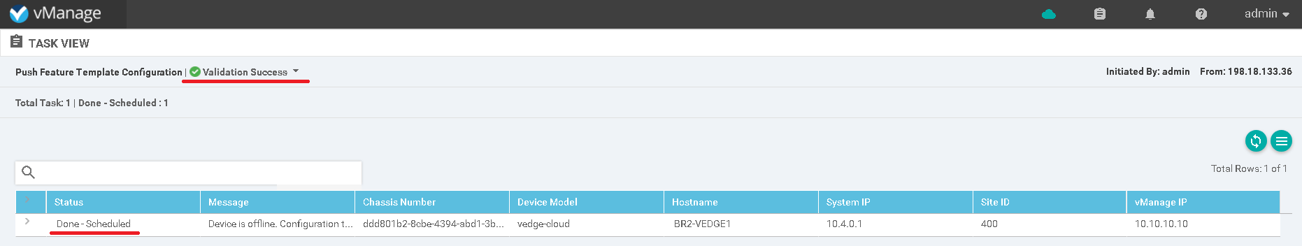
Picture 4- Template attached
Finally everything was fine and device receive complete configuration according to pushed template.
Picture 5 – vManage status after vEdge attachment
When we have parts of SDWAN connected, we can go forward with the planning and configuration tasks.
In next article we are going to focus on Cisco Viptela policy architecture and configuration.


Great Article !
Kind Regards,
Rashid G.
2x CCIE #33275
Hi, I want some information and some advise, could you please give your e-mail?
Please send your request to info@grandmetric.com