In previous article titled Cisco Viptela SD-WAN components and connectivity (Part 1) we focused on Viptela concept, Viptela SD-WAN components and how to authenticate the vEdges to Viptela cloud and setup basic connectivity between sites. Now is the time to overview the Viptela policies.
Viptela SD-WAN policies
Policies form an important topic while discussing about Viptela that need to be focused on. They are divided into two general categories: control and data.
Control policies are configured, applied and executed on vSmart controller to influence for instance:
- routing topology – Any to Any, Hub and Spoke, Partial mesh,
- VPN boundary – constrain VPN service to local boundary,
- service chaining – sent traffic via FW,
- traffic engineering.
Whereas, data plane policies are useful to introduce functionality such as:
- Cflowd – capturing and exporting flow data,
- NAT,
- Traffic counting.
As a general rule we should remember that control policies are deployed on vSmarts controller, however data are installed on vEdges routers.
| Action |
App-route Policy |
CFlowd Policy |
Control Policy |
Data Policy |
VPN Membership Policy |
| Configure |
vSmart |
vSmart |
vSmart |
vSmart |
vSmart |
| Apply |
vSmart |
vSmart |
vSmart |
vSmart |
vSmart |
| Execute |
vEdge |
vEdge |
vSmart |
vEdge |
vSmart |
Policy architecture
In this section we will look closely at overall policy architecture, which should be created in accordance with below sketch:
policy

 policy-type NAME

  vpn-list <vpn-list>

    sequence <n>

     match <route|tloc|vpn|site-id|other>

     action <accept|reject|drop> set <attributte><value>

     !

  default-action <accept|reject>
Where individual parameters mean:
- vpn-list – used by data policy to match on chosen applicable VPNs,
- sequence – defines each sequence, policy follows it until the first will match,
- default-action – action to take when any sequence does not match.
If we wanted to apply ready policy we could use below commands:
apply-policy

 site-list <name>

  control-policy <name><in|out>

 !

site-list <name>

  data-policy <name>

  vpn-membership <name>
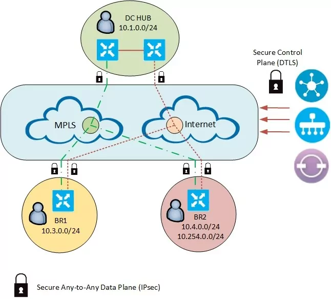
Now let’s configure basic hub and spoke topology between two branches and one hub location. We have to take into account that in the initial configuration every location is connected with each other in a full mesh scheme. In many scenarios this may be desired outcome, because we improve an overal user expierence by decreasing end to end latency. This could be usefull for example when our resources are hosted inside public clouds and explosured to the Internet. In that case we don’t have to change anything in fundamental SD-WAN approach which gives us huge advantage against an old fashioned technologies.
Nevertheless in our first scenario we will break that pattern by modification the route prefix advertisement between the branches. That means our change should also significantly decrease a number of already created tunnels.
We will work based on VPN 10 service accordingly to below topology:
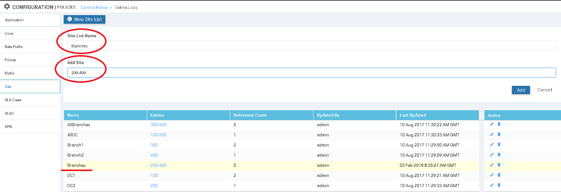
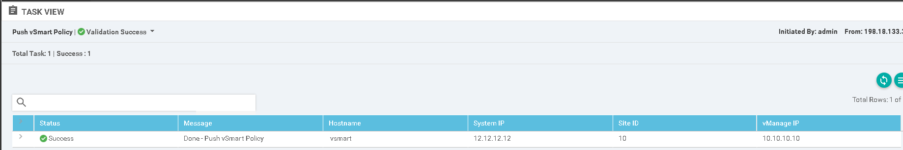
The policy configuration was generated and applied from the vManage in below order:
- Site list „Branches” was created to match on interested site id,
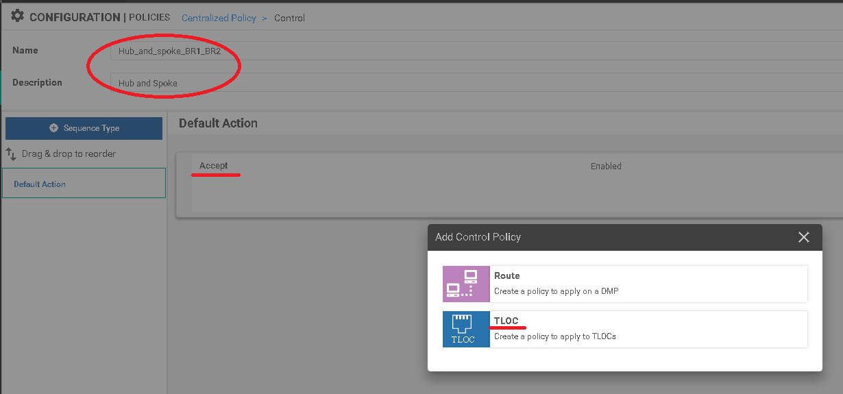
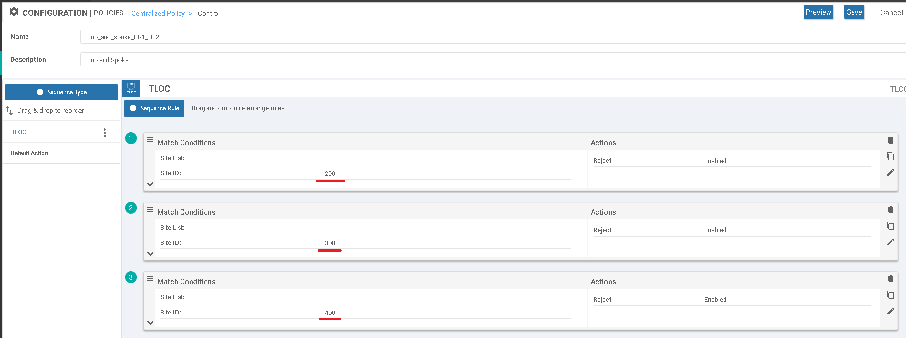
2. Control-policy „Hub_and_spoke_BR1_BR2” was defined with TLOC parametr. Three separate sequences were configired to apply new pattern per site.
c) Finally policy was pushed to the vSmart.
However, before we commence we should firstly check what is a basis network state in essential SD-WAN configuration. The previously configured device has a direct secure data connectivity to every branch and DC hub network which is confirmed by below traceroute.
BR2-VEDGE1# traceroute vpn 10 10.3.0.2

Traceroute  10.3.0.2 in VPN 10

traceroute to 10.3.0.2 (10.3.0.2), 30 hops max, 60 byte packets

 1  10.3.0.2 (10.3.0.2)  1.912 ms  2.836 ms  2.988 ms
Routing table from BR2 vEdge device, we have four default routes from both hub routers over MPLS and Internet path. Access to the second branch is also available over both lines.
BR2-VEDGE1# sh ip route vpn 10


                                            PROTOCOL  NEXTHOP     NEXTHOP          NEXTHOP

VPN    PREFIX              PROTOCOL         SUB TYPE  IF NAME     ADDR             VPN      TLOC IP          COLOR            ENCAP  STATUS

-------------------------------------------------------------------------

10     0.0.0.0/0           omp              -         -           -                -        10.1.0.1         mpls             ipsec  F,S

10     0.0.0.0/0           omp              -         -           -                -        10.1.0.1         biz-internet     ipsec  F,S

10     0.0.0.0/0           omp              -         -           -                -        10.1.0.2         mpls             ipsec  F,S

10     0.0.0.0/0           omp              -         -           -                -        10.1.0.2         biz-internet     ipsec  F,S

10     10.3.0.0/24         omp              -         -           -                -        10.3.0.1         mpls             ipsec  F,S

10     10.3.0.0/24         omp              -         -           -                -        10.3.0.1         biz-internet     ipsec  F,S

10     10.4.0.0/24         ospf             IA        ge0/2       10.4.254.254     -        -                -                -      F,S

10     10.4.254.0/24       ospf             IA        ge0/2       -                -        -                -                -      -

10     10.4.254.0/24       connected        -         ge0/2       -                -        -                -                -      F,S

10     198.18.128.0/18     omp              -         -           -                -        10.1.0.1         mpls             ipsec  F,S

10     198.18.128.0/18     omp              -         -           -                -        10.1.0.1         biz-internet     ipsec  F,S

10     198.18.128.0/18     omp              -         -           -                -        10.1.0.2         mpls             ipsec  F,S

10     198.18.128.0/18     omp              -         -           -                -        10.1.0.2         biz-internet     ipsec  F,S
A list of secured IPsec tunnels, maintained over available lines in any-to-any topology.
BR2-VEDGE1# show ipsec inbound-connections

SOURCE                                  SOURCE  DEST                                    DEST    REMOTE           REMOTE           LOCAL            LOCAL BR2-VEDGE1# show ipsec inbound-connections           NEGOTIATED

IP                                      PORT    IP                                      PORT    TLOC ADDRESS     TLOC COLOR       TLOC ADDRESS     TLOC COLOR       ENCRYPTION ALGORITHM  TC SPIs
-------------------------------------------------------

172.16.10.2                             12366   172.16.4.2                              12366   10.1.0.1         mpls             10.4.0.1         mpls             AES-GCM-256           8

172.16.12.2                             12366   172.16.4.2                              12366   10.1.0.2         mpls             10.4.0.1         mpls             AES-GCM-256           8

172.16.3.2                              12346   172.16.4.2                              12366   10.3.0.1         mpls             10.4.0.1         mpls             AES-GCM-256           8

10.10.10.2                              12346   172.16.4.2                              12366   10.3.0.2         mpls             10.4.0.1         mpls             AES-GCM-256           8

172.16.11.2                             12386   100.64.4.2                              12346   10.1.0.1         biz-internet     10.4.0.1         biz-internet     AES-GCM-256           8

172.16.13.2                             12386   100.64.4.2                              12346   10.1.0.2         biz-internet     10.4.0.1         biz-internet     AES-GCM-256           8

100.64.3.2                              12346   100.64.4.2                              12346   10.3.0.1         biz-internet     10.4.0.1         biz-internet     AES-GCM-256           8

100.64.3.2                              12940   100.64.4.2                              12346   10.3.0.2         biz-internet     10.4.0.1         biz-internet     AES-GCM-256           8
In next step, the below policy which we have earlier created on vManage will be pushed to vSmart.
policy

 control-policy Hub_and_spoke_BR1_BR2

  sequence 1

     match tloc

      site-id 200

     !

     action reject

     !

    !

  sequence 11

     match tloc

      site-id 300

     !

     action reject

     !

    !

    sequence 21

     match tloc

      site-id 400

     !

     action reject

     !

    !

  default-action accept

 !

 lists

  site-list Branches

   site-id 200-400

  !

 !

!

apply-policyBR2-VEDGE1# show ipsec inbound-connections

 site-list Branches

  control-policy Hub_and_spoke_BR1_BR2 out
As a results we stopped receiving OMP information, so the data traffic pattern changed to hub and spoke topology. Apart from that, number of secured tunnels also decreased dramatically.
BR2-VEDGE1# traceroute vpn 10 10.3.0.2

Traceroute  10.3.0.2 in VPN 10

traceroute to 10.3.0.2 (10.3.0.2), 30 hops max, 60 byte packets

 1  198.18.133.212 (198.18.133.212)  2.271 ms  3.457 ms 198.18.133.211 (198.18.133.211)  3.204 ms -> trace over HUB location

 2  10.3.0.2 (10.3.0.2)  4.826 ms  5.220 ms *
BR2-VEDGE1# show ip routes vpn 10

                                            PROTOCOL  NEXTHOP     NEXTHOP          NEXTHOP

VPN    PREFIX              PROTOCOL         SUB TYPE  IF NAME     ADDR             VPN      TLOC IP          COLOR            ENCAP  STATUS

-----------------------------------------------------------------------

10     0.0.0.0/0           omp              -         -           -                -        10.1.0.1         mpls             ipsec  F,S

10     0.0.0.0/0           omp              -         -           -                -        10.1.0.1         biz-internet     ipsec  F,S

10     0.0.0.0/0           omp              -         -           -                -        10.1.0.2         mpls             ipsec  F,S

10     0.0.0.0/0           omp              -         -           -                -        10.1.0.2         biz-internet     ipsec  F,S

10     10.4.0.0/24         ospf             IA        ge0/2       10.4.254.254     -        -                -                -      F,S

10     10.4.254.0/24       ospf             IA        ge0/2       -                -        -                -                -      -

10     10.4.254.0/24       connected        -         ge0/2       -                -        -                -                -      F,S

10     198.18.128.0/18     omp              -         -           -                -        10.1.0.1         mpls             ipsec  F,S

10     198.18.128.0/18     omp              -         -           -                -        10.1.0.1         biz-internet     ipsec  F,S

10     198.18.128.0/18     omp              -         -           -                -        10.1.0.2         mpls             ipsec  F,S

10     198.18.128.0/18     omp              -         -           -                -        10.1.0.2         biz-internet     ipsec  F,S
A list of secured IPsec tunnels, maintained over available lines in spoke to hub topology.
BR2-VEDGE1# show ipsec inbound-connections
SOURCE SOURCE DEST DEST REMOTE REMOTE LOCAL LOCAL NEGOTIATED
IP                                      PORT    IP                                      PORT    TLOC ADDRESS     TLOC COLOR       TLOC ADDRESS     TLOC COLOR       ENCRYPTION ALGORITHM  TC SPIs

---------------------------------------------------------------

172.16.10.2                             12366   172.16.4.2                              12366   10.1.0.1         mpls             10.4.0.1         mpls             AES-GCM-256           8

172.16.12.2                             12366   172.16.4.2                              12366   10.1.0.2         mpls             10.4.0.1         mpls             AES-GCM-256           8

172.16.11.2                             12386   100.64.4.2                              12346   10.1.0.1         biz-internet     10.4.0.1         biz-internet     AES-GCM-256           8

172.16.13.2                             12386   100.64.4.2                              12346   10.1.0.2         biz-internet     10.4.0.1         biz-internet     AES-GCM-256           8
In next article we are going to introduce different control and data policies, while in successive parts we will take a look on migration recommendations.


Leave a Reply