To answer the question – what is MIMO, let’s firstly take a look at the different antenna configurations.
Antenna Configurations
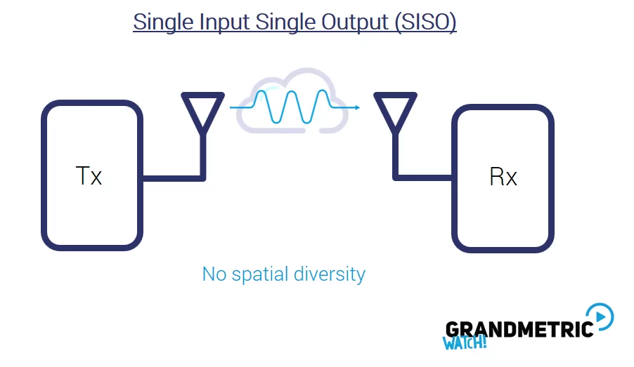
We can start with SISO (Single-Input-Single-Output) – it is when we have a single antenna at the transmitter (Tx) and single antenna at the receiver (Rx) – see the figure below.
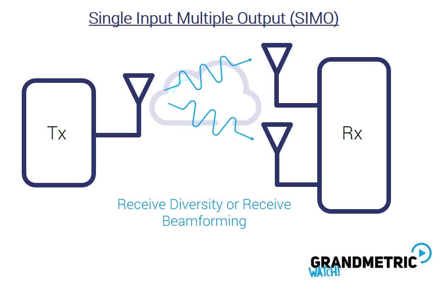
 Next, we can have multiple receive antennas, so a single transmitted signal is received independently from two different branches – and this can be used to improve link reliability by combining those received versions of the signal. Simply saying, we get 2 or more “radio links” with the “same” information, thus when there is a big distortion (e.g. deep fade) on one link, the probablity that the other is also bad is smaller. This is referred to as SIMO (Single-Input-Single-Output) and is shown in the figure below.
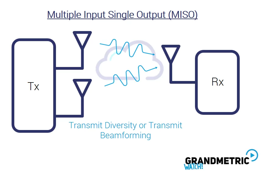
 When we make this opposite direction, we have two (or more) copies of the signal transmitted to a single receive antenna and by similiar means as in SIMO, we improve the reliability of the signal/radio link. The most common scheme for antenna/transmit diversity is to use Alamouti encoding for assuring the orthogonality between the transmission streams transmitted from the two (or more) antennas. This is known as MISO (Multiple Input-Single Output), and shown on the figure below.
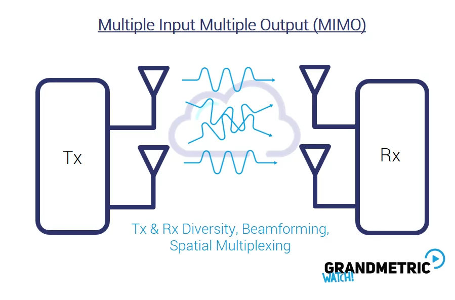
 MIMO (Multiple-Input-Multiple-Output) is the final stage, when we have both multiple Tx and Rx antennas, and by this we could also (as in the case of SIMO or MISO) improve link reliability, or do something else – that in other configurations is not possbile – i.e., transmit 2 (or more in case of more antennas) different data streams – to increase the overall system throughput (because in this case we transmit more data using the same time-frequency resources i.e., the same bandwidth and timeslots).
 MIMO
MIMO
Now, let’s get a bit more into, what actually is MIMO and why it is called MIMO as shown in the figure below.
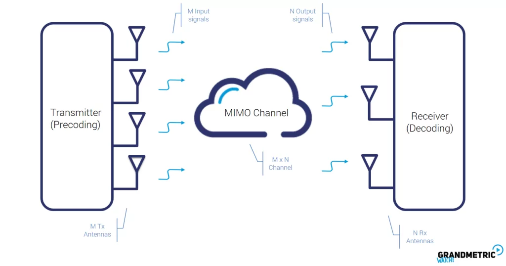
As we’ve seen in the introductory part of this blog post, in MIMO system, we have multiple antennas at the transmitter, multiple antennas at the receiver and a radio channel in-between. This is where inputs and outputs comes into play – i.e., we have Multiple Inputs (input signals TO the wireless channel) and Multiple Outputs (output signals FROM the wireless channel). When we have M transmit antennas – resulting in M inputs, and N receive antennas – resulting in N outputs – we get MxN MIMO channel. This means that we have MxN individual radio paths. Those radio paths can be utilized in different ways – to increase link throughput, reliability, or range – depending on the transmitter (and receiver) precoding (decoding) schemes. Those techniques are: spatial multiplexing, spatial diversity, or beamforming.
Other materials
To see other posts on network and wireless fundamentals see our explained section.
To subscribe to our mailing list for our online platform where you can learn all this visit GrandmetricWatch. We will let you know when it will be live.


 Next, we can have multiple receive antennas, so a single transmitted signal is received independently from two different branches – and this can be used to improve link reliability by combining those received versions of the signal. Simply saying, we get 2 or more “radio links” with the “same” information, thus when there is a big distortion (e.g. deep fade) on one link, the probablity that the other is also bad is smaller. This is referred to as SIMO (Single-Input-Single-Output) and is shown in the figure below.
 When we make this opposite direction, we have two (or more) copies of the signal transmitted to a single receive antenna and by similiar means as in SIMO, we improve the reliability of the signal/radio link. The most common scheme for antenna/transmit diversity is to use Alamouti encoding for assuring the orthogonality between the transmission streams transmitted from the two (or more) antennas. This is known as MISO (Multiple Input-Single Output), and shown on the figure below.
 MIMO (Multiple-Input-Multiple-Output) is the final stage, when we have both multiple Tx and Rx antennas, and by this we could also (as in the case of SIMO or MISO) improve link reliability, or do something else – that in other configurations is not possbile – i.e., transmit 2 (or more in case of more antennas) different data streams – to increase the overall system throughput (because in this case we transmit more data using the same time-frequency resources i.e., the same bandwidth and timeslots).
 MIMO
MIMO

