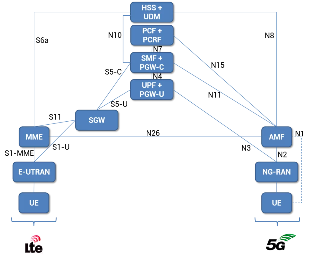
In today’s blogpost we will discuss how the interworking architecture of the new 5G system with the existing LTE systems looks like. Inter-working between 4G and 5G will play a very important role in the early deployment of 5G system, which will rely on LTE to be the anchor or underlying system. In the standalone (SA) deployment of 5G, good inter-working with the LTE system to facilitate inter-RAT mobility between the two RATs will be required.
In our previous post on 5G Core Network Functions we had introduced the Service-Based Architecture (SBA) which explained the roles played by the different network functions based on their service. For explaining the interworking architecture, we will be using the “good-old” reference point representation as used by 3GPP SA. In this architecture model we use reference points/interfaces than service exposed by NFs to comply with EPC model. We had previously covered the SBA and Reference point representation of 5G core network in our post here.
5GS and EPC interworking architecture
For interworking purposes, we require modules that can support both the legacy LTE core network (EPC) elements (HSS, PCRF, PGW etc.) as well as the Network Functions (UDM, PCF, SMF, UPF etc.) introduced in 5G. Here we use 3GPP Non-roaming architecture for describing the interworking between 5GS and EPC/E-UTRAN (to know the difference between LTE and 5G in terms of RAN and CN, check our post here) as shown in the figure below (figure is based on [1]).

Figure 1: Non-roaming architecture for interworking between 5GS and EPC/E-UTRAN [1]
Following are the important points to be noted in this architecture:
- The N26 interface has been introduced to be an inter-CN interface between the Mobility Management Entity (MME) in the LTE core network and 5GS Access and Mobility Management function (AMF) in order to enable interworking between EPC and the NG core.
- The N26 interface is meant to support the functionalities of the S10 interface (used between different LTE MMEs) that are required for interworking with 5GS. Although, the support of N26 is not mandatory. For e.g. in NSA mode when the UE will be anchored to LTE, the NW might use either EPC or 5GS (depending on the NSA mode) in which case UE context will be maintained in only one of the core networks for operation in both 4G and 5G.
- The modules such as:
- Home Subscriber Server (HSS) + Unified Data Management (UDM),
- Policy Control Function (PCF) + Policy and Charging Rules Function (PCRF),
- Packet Data Network Gateway-Control (PGW-C) + Session Management function (SMF) and
- User plane function (UPF) + Packet Data Network Gateway-User (PGW-U)
are combined entities from the EPC and 5GS supporting similar functionality, which are meant to enable interworking between them.
- If devices which do not require interworking with both EPC and 5GS access the LTE/5G system, they would be served by the individual network elements of that respective RAT.
- We can also distinguish those two systems by looking at the naming of the reference points: in LTE they are “S-something” and in 5G – “N-something”.
Summary
As shown above, the LTE EPS and 5GS can be connected to each other with the user being able to be independently registered on either of the systems and achieve mobility between the two systems using the different modules involved allowing efficient inter-working.
Inter-working between 4G and 5G systems will be an important aspect in deployment of 5G networks especially in the mmW bands (due to limited coverage) as network operators would always prefer an underlying LTE coverage to support the UEs that go out of 5G coverage. The various entities involved in this inter-working along with the architecture are quite flexible depending on how the network operator is planning to deploy their 5G networks.
References:
[1] 3GPP TS 23.501 V15.1.0 (2018-03)


Hi Marcin,
Thanks for nice summarization. I was wondering how N3 and N11 will work for non-CUPS combined PGW in EPC, given that most networks haven’t implemented CUPS. Or in Other words will CUPS be a dependency for EPC to 5GC interworking.
Thanks,
WA
Thanks for your question. I believe in the case when you don’t have CP/UP split in PGW, you will have N3 and N11 connected to PGW as if there was no split, i.e. NGRAN to PGW with N3 and AMF with N11 to PGW.