As a follow-up from our previous post on 5G Core Network (5GC) and system architecture, today I’d like to touch upon the 5G network functions (NFs) that are related to the core network. As we’ll see, some of them look very similar to the corresponding functions in the previous generations’ core networks (CN). This of course is not surprising, as the network always has to carry out some basic functions such as: communicate with the UE, store its subscription and credentials, allow access to external networks & services, provide security and manage the network access and mobility. However, we will also see some new functions, that were not present before, which are needed to enable the new network paradigms like slicing and service-based networking.
To describe the CN functions themselves, let’s first look at the system architecture from 3GPP SA2 in the following figure.
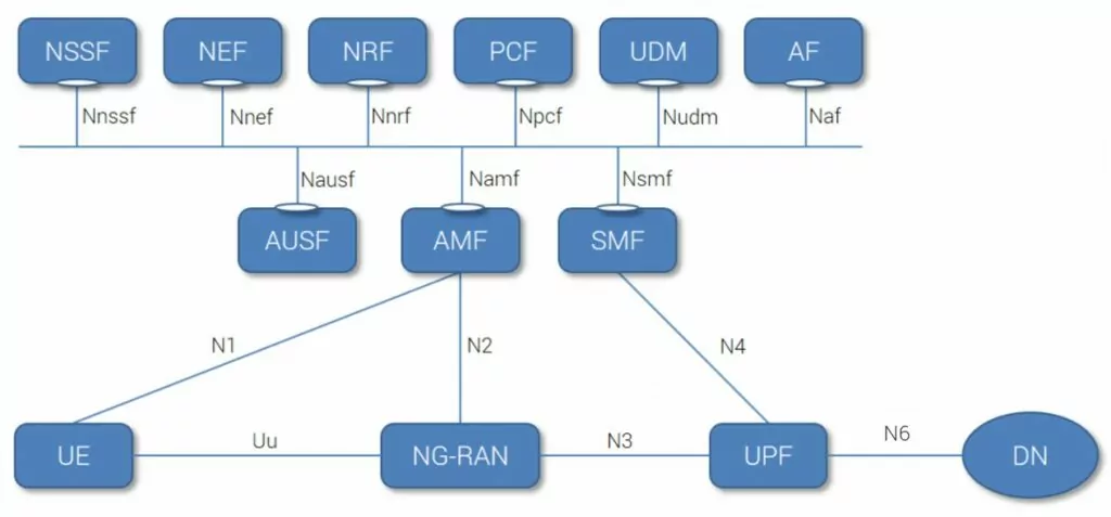
Figure 1: 5G System: Service-based architecture (SBA) [1]
We can see that part of this architecture, looks like good old LTE/3G with similar nodes and interfaces (lower part of the picture). However, the upper part of the figure (5GC Control Plane), has a “bus” and service-based interface exhibited by individual functions. This creates a so-called Service Based Architecture (SBA), in which, one CP network function (e.g. SMF) allows any other authorized NFs to access its services. According to [1], the NFs within 5GC Control Plane shall only use service-based-interfaces for their interactions.
Note: If you want to revisit the “good-old” reference point architecture representation for 5G, read our other blog on the general 5GC aspects: [5G CN Overview]. Yes, the 5G system architecture with reference points is still there.
Ok, let’s discuss a bit of the 5GC network functions themselves and what functionalities they support (note that not all functionalities of individual functions are present). The main 5G NFs are the following:
As we can see from the description of the individual NFs, some of them are modified, split, or merged versions of the good old EPC functions (like MME, SGW, PGW, HSS & PCRF) namely, AMF, SMF, PCF, UDM, AF, UPF or AUSF, but unlike EPC functions, AMF, SMF, and UPF should be access independent.
On the other hand, there are some functions that are new, related either to the concept of slicing (i.e., NSSF), to support handling multiple slices, or to the SBA itself (i.e., NEF & NRF) to support the concept of services subscription, exposure, and access.
Another thing is that in this architecture, we have a full CP & UP split in the core network, i.e. UPF supports UP data processing, while all other nodes act as CP functions (this is a bit different compared to EPC, where, e.g. PGW was acting a bit as UP and CP node, having some DHCP functionality and IP address allocation and PCEF functionality). This allows for independent scaling of CP and UP functions for the operators and for handling network slices efficiently to tailor them to support different services.
[1] 3GPP TS 23.501 V15.0.0 (2017-12) System Architecture for the 5G System (Stage 2)
[2] https://academy.5g-courses.com/courses/towards-5g-online-course
Hello,
Curious to know, what is the main reason why 3GPP choose to introduce the “Not Allowed Area” concept in 5G. Why keep the UE is kept registered while it cannot get any user (PDU) services? what is the use case behind this as we do not have this concept in 4G NAS.
Thank you.
Nitesh
Hi,
according to TS 23.501, the “Non-Allowed area” is an Area where the UE is allowed to initiate registration procedure, but no session management. If you take a look on the other two possibilities i.e.:
* in the “allowed area” the UE is registered in the network and update its location over NAS, and can initiate session (by service request),
* in the “forbidden area”, the user cannot register to the network, but can use the emergency services,
the “non-allowed area” is in the middle, i.e., the UE can register and send periodic registration update and can respond to paging from 5GC, and the emergency services are allowed, but cannot set the actual services.
This is to realise “mobility-on-demand” i.e., to support mobility only to the UEs that need it. More specifically, in a “non-allowed area” a UE is “service area restricted” based on its subscription. So, if you define a UE as “stationary”, it will only be able to reach its services within a “restricted area” and not outside.
Hope this helps,
Marcin
Dear Marcin,
Thank you for your response.
As per the above example, a “stationary UE”, if it is brought out sides its “allowed area” ( i.e. into “not allowed area”) is not going to get any user services (PDU sessions) from the network, but the registration context still remains and also its reachable for CN paging.
So you mean that it is more efficient way of handling in 5GC as compared to LTE EPC , the similar thing to achieve in LTE EPC would need reject causes but then it also removes the UE’s registration context and hence makes it unreachable ?
Thank you.
I think that in general this allows for more generic approach – i.e., you don’t have to have any special actions (as you mentioned reject causes etc.,) for specific cases, but handles different options using a single way and this suits well the slicing concept where you configure the tracking areas and allowed/non-allowed area depending on your situation. So in general I’d say that 4G could handle a lot of things that 5G is suppose to do (also slicing was sort of touched by DECOR), but as an add-ons to the baseline, while 5G should be more “generic” and “flexible” and “future proof” so that the new “cases” could be added / handled easier than modyfing a lot of 3GPP TSs’ contents.
Thank you Marcin for your valuable feedback and explanation. In sync and agree to your comments.
Kind regards,
Nitesh
Thank you Marcin for your valuable feedback and explanation. In sync and agree to your comments.
Kind regards,
Nitesh
One of the good use case of “Not Allowed Area” is in India.
Many times, regulatory bodies ask carriers for barring of voice and data services selectively in a given geographic area – due to law and order concerns.
Services are allowed after a certain time window, which is intimated by the regulators on-demand.
In LTE, for such cases – we achieve service barring at many levels – TAC level, Cell-ID level as well as at the APN level, all orchestrated by the PCRF. Only emergency services are allowed in such cases.
In 5G, these use cases will become simpler to handle due to the “Not Allowed Area”,
Completely agree, till 3G or 4G complete system access barring is the only solution on IMSI level, then one needs to worry about Inroamer barring etc and service type barring as well.
With “Not allowed area” this can be resolved
[…] many more of CP functions in the full 5GC architecture – see our posts discussing them here: 5G Core Network Functions and 5G Core Network […]
[…] many more of CP functions in the full 5GC architecture – see our posts discussing this here: 5G Core Network Functions and 5G Core Network […]
What is the diference between HSS and UDM?
There is any diference bwtween HSS and UDM with respect to interface and protocol, Could we use the same HSS for 5G?
Regards,
Luis Di Nisio
Core Engineer
Hi Luis,
UDM has only part of the original HSS functionality and the interface is also different: to backup this you can check this presentation by ITU showing mapping of the 4G CN nodes to 5G CN: https://www.itu.int/en/ITU-T/Workshops-and-Seminars/201707/Documents/Joe-Wilke-%205G%20Network%20Architecture%20and%20FMC.pdf
In the case of using HSS for 5G, it depends on what you actually mean by 5G – if its the full blown 5GS (5GC + NGRAN), the related nodes are UDM and AUSF and they use SBA principles with service type interfaces. While if you mean 5G by using NSA with 5G NR being suplement to LTE, the core network comes from EPC thus the corresponding node is HSS.
Hope this helps,
Marcin
Do you know the interface name between AMF & NRF?
I am aware of Nnrf but looking for exact number, like N2 etc.
Dear Adnan,
thanks for the question. NRF is present “only” in the service based architecture version of 5GC. I.e. there is no defined reference point (“like N2”) for NRF to any of the other NFs within the home domain (see 3GPP TS23.501 for reference). The only point where NRF is connected via reference point (“like N2”), is where we have a roaming scenario and NRF in home network connects to NRF in visited network and both NRFs are connected with N27.
Hope this clarifies the issue.
/Marcin
What does it mean access independent in the following sentence?
“unlike EPC functions, AMF, SMF and UPF should be access independent”
They will work independently of the RAN type (2G, 3G, 4G, 5G)? Backwards & forwards compatibility?
Hi Ruben,
thanks for your question. Access independent means two things in this context:
* first – it enables independent evolution of the access network from the core network (i.e., separates RAN from CN);
* second – it is access independent, because it allows the evolved LTE connect to the 5GC and NG-RAN connect to the same 5GC. As per TR23.799, the 5G System shall support the NR, the Evolved LTE, and non-3GPP access types. GERAN and UTRAN are not supported.
Hope this helps,
Marcin
HI Marcin Dryjanski,
Just wondering how SMF can allocate the UE IP address for MEC cases(Ex: LIPA).
In LTE, PGW allocates the IP address, in normal cases.
In MEC cases, there is a provision to have the PGW locally at RAN(LGW). Which allocates the local IP address.
Is there similar concept adopted in 5G as well?
Thanks,
Aravind Sirsikar
Hi Aravind,
The SMF either allocates UE IP address or acts as “sort-of” proxy for the IP address allocation when the address is allocated by external data network (according to the below quotes, the SMF is always in the process).
According to 3GPP TS23.501: “The SMF shall process the UE IP address management related messages, maintain the corresponding state information and provide the response messages to the UE. In the case that the UE IP address is obtained from the external data network, additionally, the SMF shall also send the allocation, renewal and release related request messages to the external data network and maintain the corresponding state information.”
According to 3GPP TS 29.561: “The 3GPP network may obtain IP address via external DHCP server during the PDU establishment procedure, the SMF acts a DHCP server towards the UE and it acts as a DHCP client towards the external DHCP server. ”
And according to ETSI White Paper No. 28: “The SMF is in a key position with its large number of responsibilities. Some functionality provided by the SMF includes session management, IP address allocation and management, DHCP services, selection/re-selection and control of the UPF, configuring the traffic rules for the UPF, lawful interception for session management events, charging and support for roaming. As MEC services may be offered in both centralized and edge clouds, the SMF plays a critical role due to its role in selecting and controlling the UPF and configuring its rules for traffic steering. The SMF exposes service operations to allow MEC as a 5G AF to manage the PDU sessions, control the policy settings and traffic rules as well as to subscribe to notifications on session management events.”
Hope this helps,
Marcin
Dear Marchin,
Do you have any article for MEC? How does it work and help for low latency?
Thanks
Sandeep Agarwal
Thanks for the question Sandeep,
regarding MEC, you can check out this article: http://www.eurecom.fr/fr/publication/5218/download/comsys-publi-5218.pdf (a scientific one about MEC in LTE for low latency), and a short one from ETSI: https://www.etsi.org/images/files/ETSIWhitePapers/etsi_wp28_mec_in_5G_FINAL.pdf
I would recommend those two.
Hope this helps,
Marcin
Hi Marchin,
LBO ( Local Breakout) is old concept from LTE or 3G times but it was not implemented by most of the MNOs because of billing complications. In 5G is LBO different than 4G LBO? Do you think MNOs would implement it in 5G to reduce latency or it should not be implemented again same as earlier?
Thanks
Sandeep Agarwal
Hi Sandeep,
an interesting question. I believe this time it could be a little different, as 5G can use the MEC concept and a native tight interworking with Wi-Fi, while in LTE LBO was added on top of the existing infrastructure.
Dear Marcin,
I came across this informative post while searching for vNFs in the new 5G architecture. I have some questions regarding the vNF forwarding graph for 5G. In the new architecture, if a user A has to make a call or if he has to connect to the Internet, in which sequence are these vNFs traversed in order to accomplish this task? For 4G, the sequence in which the traffic traverses the vNFs is as follows:
Call : userA – EPC – IMS – SBC
Conn. to Internet: userA – EPC – IPX
Look forward to your reply.
Thank you
Varun
Dear Varun,
thanks for your question.
If you are asking about the flow for the so-called, “PDU session establishment procedure” (which is obtaining the actual service), the flow is as follows:
UE – AMF – SMF – UPF – UDM – DN (Data network – which can be the Internet or something different)
whereas for the actual data/packet flow:
UE – UPF (or set of UPFs) – DN
and the UPF is controlled by SMF.
For the details, please take a look onto TS 23.502
Hope this helps,
Marcin
Hi Marchin,
Who will be publishing UE ip’s to external DN, is it done by SMF or UPF ?
As ip pools are maintained/configured in SMF, SMF will be advertising these IP’s?
Thanks
Kantu
Hi Kantu,
SMF is the responsible entity, as it handles the CP aspects of the connection/session: “Session Management function (SMF) supports: session management (session establishment, modification, release), UE IP address allocation & management, DHCP functions, termination of NAS signalling related to session management, DL data notification, traffic steering configuration for UPF for proper traffic routing. ”
UPF only holds the UP aspects.
Hope this helps,
Marcin
Hi Marcin,
Thank you for this very information post.
I would like to know from you, if it is actually possible for an AMF belonging to a MNO to talk to another AMF of another MNO.
For that matter, can AMFs of same MNO communicate between each other , exchanging information of UEs etc?
Regards,
Nanda
P.S : MNO -> Mobile Network Operator.
Dear Nanda,
Thanks for your question.
AMFs can be interconnected (using N14 interface) and when interconnected, they should belong to the same MNO.
In the roaming cases (either national or international), the connections between the home and visited operators are: AMF and AUSF; Home-PCF and Visited-PCF; Home-SMF and Visited-SMF; and UPFs (in the home-routed scenario).
Hope this helps,
Marcin
Hi Marcin,
May I know what is the main function of Data Network in 5G system? Is it similar to a server? I google but I couldn’t find the answer.
Actually, what is the main function of the core network and how exactly it functions?
Thank You & Best Regards,
Emi.
Hi Emi,
Data Network (DN) is a 5G term for, what was called PDN in 4G, i.e. an IMS, Internet, etc. It is located outside the core network – belonging to the “services” part of the system.
If you want to google things like that, it’s always good to phrase it with context, like “5G DN”, or “3GPP Data Network 5G” etc.
Hope this helps,
Marcin
Dear Marcin,
Thank You for your sharing. I have another few questions…
1. What are the limitations of 5G System? Where can I get more information regarding this?
2. How to understand the 5G System? 5GS is a very big area. I already read the 5G White Paper but I still couldn’t understand the system better.
Thank You & Best Regards,
Emi.
Dear Emi,
thanks for your questions.
For both questions, the most relevant place is the 3GPP web, on which you can find all the details. On 3GPP web, in turn, there is a plenty of documents, while the 5G related ones are in 38-series (regarding RAN and air interface), and 23-series (regarding Core network). If you are new to the topic, then I recommend you start with 3GPP TS 38.300 (5G radio and RAN overview) and 3GPP TS 23.501 (5G core network overview and architecture).
Best,
Marcin
Very nice blog and amazing discussion and answers to all queries of audiences in comments. Great job Marcin for being so considerate & helpful .
Just observed few typo – 1) Please change interface N5 to N6 between UPF & DN .
2) In 5G NFs definitions its written for SMF – “(AMF has part of the MME and PGW functionality from EPC world)” . So rather it should be “(SMF has part of the MME, PGW-CP & SGW-CP functionality from EPC world).
Thanks for all knowledge sharing that you do 🙂
Thanks, Ashutosh for your kind words! I’m glad it’s helpful.
Regarding your comments – thanks for spotting! Updated.
Dear Marcin,
Is there any function in 5GC to allocate IP address range OR multiple IP’s to a single UE. Browsed through some 3GPP documents, could not find any relevant reference.
Customer is curious on how to assign IP range to UE (for example router) for 5GC NW management purpose and wondering if SMF/UPF have some feature OR support this if assigned by external entities.
Thanks for all the insights that you share here.
Dear Subhamay,
thanks for your question.
As far as I’m aware, the multiple IP addresses can be used for a UE supporting the MPTCP Functionality, see in [TS23.501, section 5.32.6.2.1], and per the mentioned section, the following paragraph is included:
“If the UE indicates it is capable of supporting the MPTCP functionality, as described in clause 5.32.2, and the network agrees to enable the MPTCP functionality for the MA PDU Session then:
(…)
ii) The network allocates to UE one IP address/prefix for the MA PDU Session and two additional IP addresses/prefixes, called “link-specific multipath” addresses/prefixes; one associated with 3GPP access and another associated with the non-3GPP access. In the UE, these two IP addresses/prefixes are used only by the MPTCP functionality. Each “link-specific multipath” address/prefix assigned to UE may not be routable via N6. The MPTCP functionality in the UE and the MPTCP Proxy functionality in the UPF shall use the “link-specific multipath” addresses/prefixes for subflows over non-3GPP access and over 3GPP access and MPTCP Proxy functionality shall use the IP address/prefix of the MA PDU session for the communication with the final destination. In Figure 5.32.6.1-1, the IP@3 corresponds to the IP address of the MA PDU Session and the IP@1 and IP@2 correspond to the “link-specific multipath” IP addresses. The following UE IP address management applies:
– The MA PDU IP address/prefix shall be provided to the UE via mechanisms defined in clause 5.8.2.2.
– The “link-specific multipath” IP addresses/prefixes shall be allocated by the UPF and shall be provided to the
UE via SM NAS signalling.”
Hope this helps,
/Marcin