Introduction
You may wonder why I’m writing about Dual Connectivity. After all, it comes from LTE in Rel-12, when we are currently within the Rel-16/17 timeframe. The reason for this is that the DC from LTE is treated as a baseline. The enhanced version is incorporated within 5G as one of the main features to allow the so-called Multi-RAT DC (MR-DC). If we look from a broader perspective, we have a multitude of use cases for DC, including LTE-DC, NR-DC, LTE-NR-DC, NR-LTE-DC, LWA. Therefore, this post aims at shedding light on the different aspects of DC, being the legacy feature, which can be extrapolated towards the current situation.
Dual Connectivity (DC)
Dual Connectivity (DC) is an LTE Rel-12 feature that enables aggregation of two radio links with non-ideal backhaul without low-latency requirements. To allow this, the links are aggregated at the PDCP level, combining PDCP PDUs. This is different compared to CA (Carrier Aggregation) that combines MAC-layer blocks. The figure below shows the differences between DC and CA.
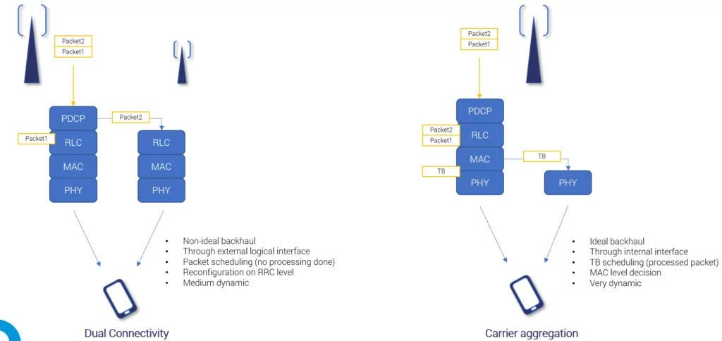
For resource aggregation, UE in RRC_CONNECTED state is allocated two radio links from two different network nodes utilizing regular X2-connectivity and connected via a non-ideal backhaul. The nodes play different roles. Macro-Cell serves as mobility and signaling anchor (called Master eNB, terminating S1-MME) and Small Cell serves as a local “capacity booster” (called Secondary eNB, providing additional radio resources for UE). The two resource sets involved in the process are termed as Master Cell Group (MCG, associated with MeNB, and comprising of a PCell and zero, one or more SCells) and Secondary Cell Group (SCG, associated with SeNB, and comprising of PSCell (Primary SCell) and zero, one or more SCells).
Dual Connectivity can improve user throughput and mobility robustness by allowing users to be connected simultaneously to MCG and SCG. It also supports load balancing between MCG and SCG resources.
Protocol architecture within DC depends on the bearer set up. There are three bearer types, namely MCG bearer, SCG bearer, and split bearer (see the figure below, reproduced from 3GPP TS 36.300 [1]). We talk about MCG bearer when radio protocols are located only at the MeNB. The split bearer – when radio protocol is in both MeNB and SeNB, and SCG bearer – when radio protocols are located only at SeNB.

Dual Connectivity Operation
Dual Connectivity procedures expand the mobility framework from a handover between two cells, incorporating the following procedures [1]:
- SeNB addition
- SeNB modification (intra MeNB handover involving SCG change)
- SeNB release
- Change of SeNB
- MeNB to eNB change (DC-to-Single Connectivity)
- SCG change
- eNB to MeNB change (Single Connectivity-to-DC)
- Inter-MeNB handover without SeNB change
There are several implications coming out of DC [2]:
- In the Split bearer case, DC requires flow control i.e., additional RRM algorithm, scheduling PDCP PDUs to different links;
- Scheduling of individual packets at each link is performed separately and independently of each other and thus can be optimized at each link according to individual channel characteristics;
- The advantage of this design is that the signaling overhead can be decreased by means of reduction of the number of handovers, as the CP/UP split concept can be realized by keeping the user context at MeNB, while flexibly allocating radio resources among MeNB and different SeNBs;
- There is a single link for signaling, always at MeNB. There is a risk of dropping the connection when the MeNB link deteriorates, even if SeNB has a good channel quality;
- The Traffic Steering/Mobility Load Balancing framework is expanded from the intra/inter-frequency/inter-RAT handover towards a more holistic framework with multiple options.
Example DC Configuration
Pre-requisites needed for SCG activation:
- X2 Interface setup (If ANR is there, manual effort not required)
- To perform addition/deletion
- To share load balancing info
- Neighbor relation definition between MCG & SCG
- PCI addition of SCG (SeNB) in the DC feature configuration data
- A4 Events Parameters (used for addition process)
- Count for Users who can use DC features
- UE Capability to support DC feature (EUTRAN Bands for DC)
Addition/Deletion of SCG/SeNBs may happen based on the following conditions:
- Coverage or Quality based: RSRP / SINR measurements
- RSRP > X dBm (A4 Event)
- SINR > Y dB
- Data Need-Based: Buffer size at PDCP Level / UE Request
- Deletion may also happen based on UE Inactivity
- We can further include a prohibit timer for addition/deletion to avoid ping-pong effect.
- Addition request may not be entertained in the condition if SCG/SeNB is overloaded or the number of DC users exceeds the limit.
References
[1] 3GPP TS 36.300
[2] M. Rahnema, M. Dryjanski, “From LTE to LTE-Advanced Pro and 5G”, Artech House, 2017.
Note: ETSI is the copyright holder of LTE, LTE-Advanced, and LTE Advanced Pro and 5G Logos. LTE is a trademark of ETSI. Grandmetric is authorized to use the LTE, LTE-Advanced, LTE-Advanced Pro, and 5G logos and the acronym LTE.


Leave a Reply