Menu

Poland

GRANDMETRIC Sp. z o.o.
ul. Metalowa 5, 60-118 Poznań, Poland
NIP 7792433527
+48 61 271 04 43
info@grandmetric.com

Sweden

Drottninggatan 86
111 36 Stockholm
+46 762 041 514
info@grandmetric.com

UK

Grandmetric LTD
Office 584b
182-184 High Street North
London
E6 2JA
+44 20 3321 5276
info@grandmetric.com

US Region

Grandmetric LLC
Lewes DE 19958
16192 Coastal Hwy USA
EIN: 98-1615498
+1 302 691 94 10
info@grandmetric.com

  • en
  • pl
  • LTE and 5G Differences: Function Decomposition Between RAN and CN

    LTE and 5G Differences: Function Decomposition Between RAN and CN

    Date: 21.05.2018

    Category: 5G, Mobile Networks


    Hi there!

    Let’s take a quick look at some of the differences between LTE and 5G (maybe I’ll make a series out of this, who knows :)) and today it is in the area of functional splits between RAN and Core Network.


    LTE vs 5G: Functional Splits

    The figures below show high level splits of selected functionalities of the main “network functions/nodes” in both systems (discussing it from the 3GPP RAN3 WG perspective) from which we can make some conclusions on the differences between those two systems. For the sake of clarity and from puristic reasons let’s use the names EPS (Evolved Packed System) and 5GS (5G System). (However, for the simplicity reasons, we’ll use the LTE term interchangeably with EPS :)).

    EPS Functions Split

    The first figure captures basic functional split between E-UTRAN and EPC (within EPS) where the main nodes include eNB, MME, SGW and PGW (based on figure from [1]). eNB is responsible for management of the radio resources, radio connectivity and connected mode mobility.

    MME is the main signalling node in EPC covering NAS level signalling, idle state mobility and session management. On the other end SGW and PGW mostly deal with UP packet processing, but also cover other aspects like UE IP address allocation, packet filtering and accouting data generation – which more fits into Control Plane. Here we also have S1 interface that has two versions: S1-U and S1-C to capture the UP and CP split on the borderline between RAN and CN.

    If you want to have a full list of functions between those network elements in LTE refer to [1] chapter 4.1.
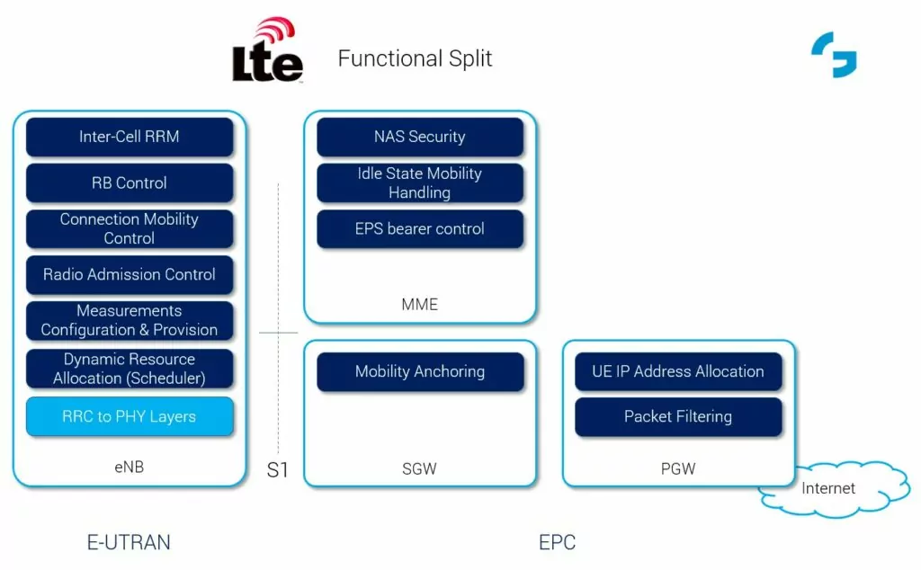
    LTE Functional Split

    5G System Functions Split

    The second figure (based on figure from [2]) presents a similiar approach to show the functionality placement onto different network functions/elements within 5G system (5GS).

    Here the RAN (called NG-RAN) consists of gNBs (NR base stations) and/or ng-eNBs (LTE base stations supporting 5G Core Network). As we can see from the figure, most of the functionality is similiar to what we have in eNB from E-UTRAN, with some differences not shown in the figure, like support for Network Slicing or QoS related aspects (QoS flow management and mapping to radio bearers) and tight interworking between NR and E-UTRA.

    Now, in the core network (called here 5GC) we have some more basic differences vs what we have in EPC. First, in 5G we have a full CP/UP separation, where the upper functions provide solely CP, where, compared to LTE, 3GPP took out the session management from MME and UE IP Address – aspects from PGW and put to Session Management Function (SMF). What is left from MME, namely mobility management and network access, registration, security etc., is put in a separate node, called Access and Mobility Management Function (AMF). On the data plane side, we have a network function performing purely packet processing and transmission operations, called simply User Plane Function (UPF). In terms of the interface between NG-RAN and 5GC, similiar to EPS world, we have an interface called NG, also using two versions: NG-C and NG-U connected to AMF and UPF respectively. (However, if you speak to 3GPP SA2 representatives, you may hear that those are termed: N2 and N3 reference points).

    If you want to have a full list of functions between those network elements refer to [2] chapter 4.2. Also, note that there are many more of CP functions in the full 5GC architecture – see our posts discussing this here: 5G Core Network Functions and 5G Core Network Overview.
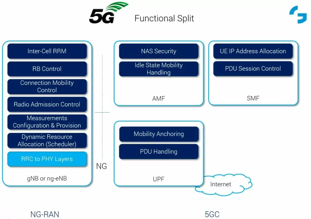
    5G Functional Split


    LTE and 5G Differences Summary

    Now, if you’d ask me to summarize the differences from high level perspective, I’d answer with the following items:

    • Firstly, the nomenclature:
      • in LTE we have a simple pure naming using the “Evolved” term: E-UTRA (radio interface), eNB (base station), E-UTRAN (RAN), EPC (CN), EPS (system);
      • in 5G, in turn, we have many different names with a variation of “5G” and “new/next generation”: NR (radio interface), gNB or ng-eNB (base station), NG-RAN (RAN), 5GC (CN), 5GS (system);
    • Secondly, the function split in the CN:
      • in LTE we have a bit mixed CP and UP functions between different network nodes;
      • in 5G we have a full CP/UP split, with many CP network functions and UPF, doing solely data plane processing;
    • Thirdly, in 5G we have some new functionality not present before, like:
      • network slicing implying different configurations of RAN
      • new QoS framework with flows instead of end-to-end bearers
      • new approach to 5GC using service based architecture (SBA) concept;
    • … and more that I’ll try to write about in the next posts (if I decide to make a series out of this :)).

    Hope this post helps you to get some answers, if you have questions like: “what 5G actually is” and “how is 5G different from 4G” or similiar.

    If you are interested in some other comparisons (or rather comparisons of other aspects, like architecture, PHY layer, air interface, …) between those two systems, please comment below and I’ll try my best to adress those in the future.


    References

    [1] 3GPP TS 36.300 “EUTRA and EUTRAN, Overall Description”

    [2] 3GPP TS 38.300 “NR and NG-RAN, Overall Description”

    Author

    Marcin Dryjanski, Ph.D.

    Marcin Dryjanski received his Ph.D. in telecommunications from the Poznan University of Technology in September 2019. During the past 15 years, Marcin has served as R&D Engineer, Lead Researcher, R&D Consultant, Technical Trainer, Technical Leader and Board Member. He has been providing expert-level courses in the area of 5G/LTE/LTE-Advanced for leading mobile operators and vendors. In addition to that, Marcin was a work-package leader in EU-funded research projects aiming at radio interface design for 5G including FP-7 5GNOW and FP-7 SOLDER. He co-authored a number of research papers targeting 5G radio interface design and a book "From LTE to LTE-Advanced Pro and 5G" published by Artech House. Marcin is co-founder of Grandmetric and co-founder and CEO at Rimedo Labs, currently focusing on Open RAN systems.

    20 Comments
    Hiep Nguyen
    22 May 2018 at 09:33

    Hi Marcin,
    Could you elaborate more on the CP/UP split in 5G.
    In 4G, the NAS is sole carried out by the MME and the S/P-GW is responsible for the U-plane.
    I think in LTE, the CP and UP are already splitted.
    I am not clear about the CP-UP split differences in 5G NR comparing to 4G.

     
    Marcin Dryjanski
    22 May 2018 at 10:25

    Hi,

    thanks for your comment. Yes, you are right, in LTE, signalling between UE and network is carried by MME using NAS, and S/P-GW is responsible for U-Plane. However, some of the session related signalling is carried by S/P-GW, thus the S5 interface, between S-GW and P-GW has both C- and U-Plane part, e.g., UE IP address allocation that has to be transferred from P-GW to S-GW that then passes it to MME (also session setup from PGW to MME is transferred through SGW). However, in latest releases of LTE-A Pro there is a feature standardized (i.e. CUPS) to make this split more complete.

    In 5GS, we clearly have this separation where SMF takes some of the “PGW’s CP-like” functions and leaves the packet-only processing aspects to UPF.

    Hope this helps,
    Marcin

     
    sumit
    22 May 2018 at 13:56

    Hi Marcin, thanks a lot sharing difference. can you please share the info of synchronization of LTE & 5G? i.e. how the PSS and SSS are dfferent in 5G and how UE latches on 5G nodeB? also if possible 5G throughput calculation for Sub 6 radio i.e. 3.5 Mhz with 100 Mhz BW?

    thanks in advance.
    Regards,
    Sumit

     
    Marcin Dryjanski
    22 May 2018 at 14:22

    Thanks Sumit for your question.

    This could be another post on the details between LTE and 5G NR as it’s not a short answer.

    So, please stay connected, and I’ll put that onto my agenda for future posts.

    BTW – for a quick answer on throughput calculation, you can check out this web: http://niviuk.free.fr/nr_capability.php

    /Marcin

     
    Ashutosh Kaushik
    22 May 2018 at 15:18

    Well done !!

     
    Marcin Dryjanski
    23 May 2018 at 17:46

    Thanks!

     
    Jatin Valecha
    26 May 2018 at 15:24

    Nice explanation !! Marcin ,Is there any reference documents available to study in detail .

     
    Marcin Dryjanski
    28 May 2018 at 07:37

    Thanks!

    I’ve put the sources (3GPP Specs numbers) in the “References” below the post – and those would be the good starting points for further read. Please let me know, if you need anything else.

     
    Ashutosh Kaushik
    5 June 2018 at 13:35

    Hi Marcin,

    Why we have mobility anchoring in UPF , which mobility it refers to & why not it is in AMF ?
    We already have idle mode mobility in AMF & I guess in LTE even connected mode mobility related signalling was also in MME ?

     
    Marcin Dryjanski
    5 June 2018 at 15:26

    Hi Ashutosh,

    thanks for your question. The UPF is responsible for PDU session anchoring – i.e. when the UE moves around and changes cells/gNBs the IP session is kept (and UPF switches the path between gNBs when needed), so it strictly relates to UP packet forwarding – similar to what was done in LTE by SGW. However, traffic forwarding rules and policies are provided by SMF.

    Hope this clarifies the issue.
    /Marcin

     
    Muktheshwar
    3 May 2019 at 20:51

    Thanks for your insight into the differences. It does means that there is no GTP-C is used in 5G right ?

     
    Marcin Dryjanski
    8 May 2019 at 13:33

    That’s correct, there is no GTP-C used in 5G-Core Network (5GC) for communication between NFs, as it’s service based, and the communication protocol is based on HTTP/2 (on top of TCP/IP).

     
    Nadeem
    18 May 2019 at 11:15

    Hi Marcin,

    It was a good high-level summary of the differences of 4G & 5G technology.
    However, regarding modulation side, is it 64 QAM or higher in 5G – any progress there? To make a better spectral-efficiency for 5G?
    You mentioned about Network slicing & QoS mainly. Can you give more info still on high level…
    I am more interested in RAN (Radio side).
    Thanks in advance.

    Br
    Nadeem

     
    Marcin Dryjanski
    22 May 2019 at 09:14

    Dear Nadeem,

    Regarding the modulation, as of current specifications, the NR maximum supported modulation scheme is 256QAM (3GPP TS38.211), while the most recent option for LTE is 1024QAM (3GPP TS36.211) – Rel.15.

    Regarding the other features you asked about, please refer to other posts on our blog:
    * slicing overview: https://www.grandmetric.com/2016/07/05/5g-norma-vs-ip-networks-techniques-slicing/
    * details on RAN complexity: https://www.grandmetric.com/blog/2018/07/14/lte-and-5g-differences-system-complexity/
    * energy efficiency schemes: https://www.grandmetric.com/2016/10/16/energy-efficiency-for-5g-networks/

    Hope this helps!
    Marcin

     
    Sunil
    7 July 2019 at 14:21

    Hi Marcin,
    Can you briefly explain the 5G Basic procedure(i.e overall sequence) from the time UE is on.

     
    Marcin Dryjanski
    15 July 2019 at 23:22

    Hi Sunil,

    you can find the detailed description of the registration procedure (i.e. the steps the UE takes when it comes “alive” the first time in the network) in 3GPP TS 23.502, section 4.2.2 (figure 4.2.2.2.2-1 – explaining that from the L3/NAS perspective).

    But in general:
    * UE firstly looks for the sync signals and PBCH (in NR, this is generally called SS-block), and reads the configuration from PBCH and SIB1,
    * then UE attempts Random Access Procedure (sends preamble on configured PRACH resources, receives RAR and sends first RRC message)
    * when successful, the Network configures signalling connection on RRC
    * then the registration procedure starts – i.e. the UE sends the NAS message to AMF and the procedure in 23.501 follows.

    Hope this helps,
    Marcin

     
    Trung Le
    25 July 2019 at 11:58

    Hi Marcin,

    It is a useful article. Do you know the benefit of a full CP/UP split?
    Thanks,
    Trung.

     
    Marcin Dryjanski
    26 August 2019 at 12:07

    Hi, the major benefit of the CP/UP split is that the operators can scale the capacity of both (CP and UP) separately and depending on the needs. Secondly the functions of CP and UP can be deployed separately and where needed, e.g. when you have the requirement to have the UP close to the users (e.g. at the edge) it can be placed there, without the impact on the related CP functions.

    Hope this helps,
    Marcin


    Leave a Reply

    Your email address will not be published. Required fields are marked *


    Grandmetric