Introduction to Shadowing
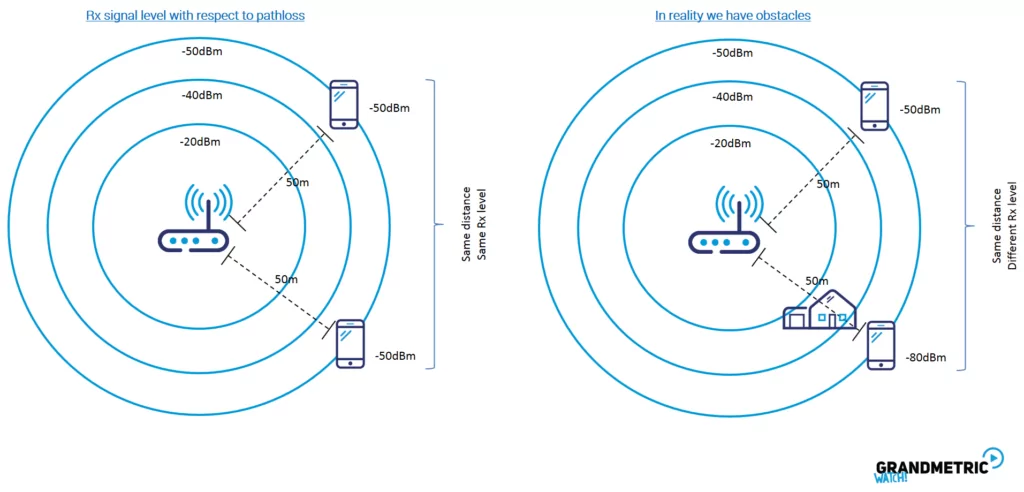
When we take an omnidirectional antenna in a scenario shown on the left side in the figure above, and assume line-of-sight, LOS (i.e., that transmit and receive antennas „see each other”), we should expect that the received signal level will be the same at the same distance independently on the receiver location around the transmitter.
That would be true, if there are no obstacles and we have a plain surface. But the reality is not that „rose” i.e., in real life scenarios we have obstacles (see the right side of the figure above) – e.g., in our case, a house – so that the receiver is at the same distance from the transmitter, but in a different location (different angle) is experiencing much weaker received signal level. This effect happens, when there is a large object such as a building or a hill “blurring” the main radio path between the receiver and the transmitter. This is known as shadowing (shadow-fading), or slow-fading, as it makes the signal level slowly changing with the time (as e.g., the building is “always” there).
Simulation Examples
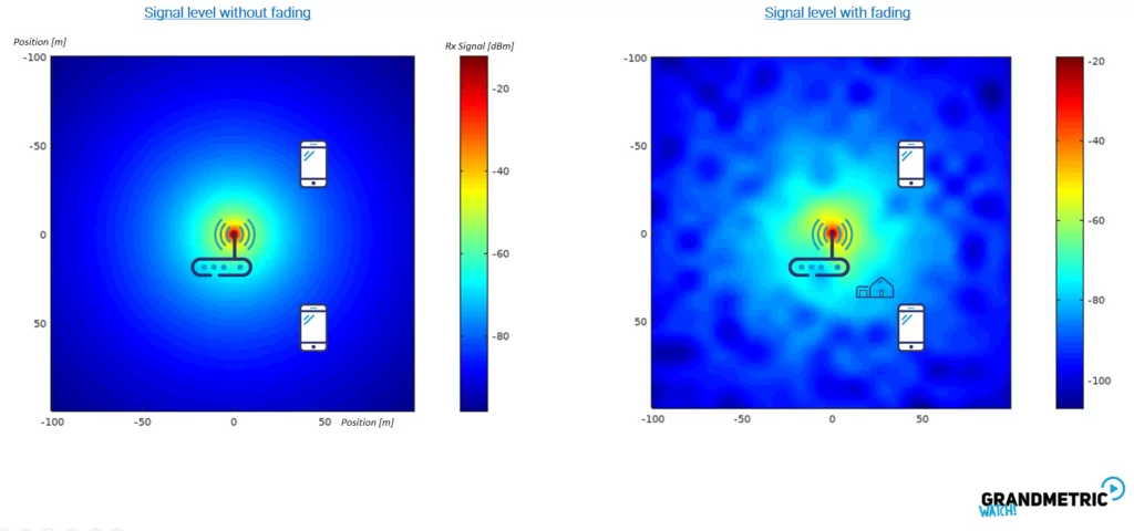
The figure below shows the same example of the signal parameters using simple simulation model. Here we have different signal levels put on a map with different colours – the warmer the colour the higher the received signal level. We see the „fluctuation of the colours on the right figure (i.e., the one with fading implemented).
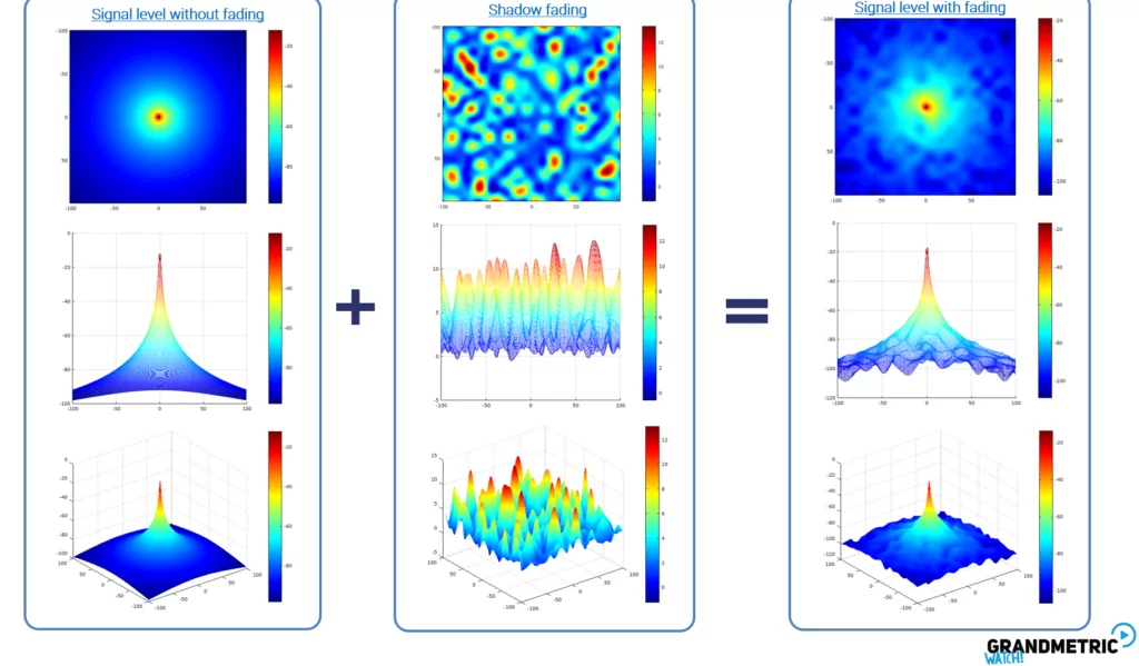
 The same example is shown with a little bit more details and different perspectives on the next figure – seen from the top, from the side and at a certain angle in 3D.

In the left part of the figure, we have a nice clean shape of the signal level, where there is no signal fading. The central part shows the shadow-fading itself – a random process being a variation of the attenuation of the signal depending on the receiver position, time and carrier frequency. We could actually see, that we have larger or smaller power decrease in the signal. This is due to the fact that we could have at a certain distance a building that obscures the signal, and on the other angle at the same distance, a mountain that smoothes the signal level. Finally, the signal level fluctuations are subtracted to the nice / clean signal levels coming from pathloss formulas and give in the result (rightmost figure) a more „hilly terrain”.
Other materials
To see other posts on network and wireless fundamentals see our explained section.
To subscribe to our mailing list for our online platform where you can learn all this visit GrandmetricWatch. We will let you know when it will be live.


 The same example is shown with a little bit more details and different perspectives on the next figure – seen from the top, from the side and at a certain angle in 3D.


